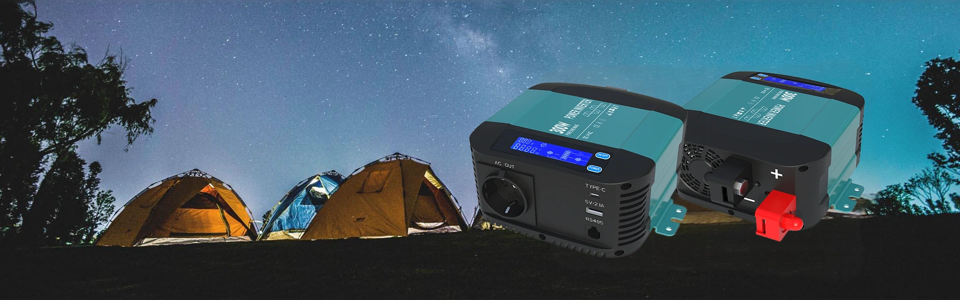
Modern off‑grid and emergency power systems demand hardware that combines stable AC conversion, integrated battery charging and comprehensive electrical safeguards. This article explores core functionality, practical deployment scenarios, built‑in protective mechanisms and communication capabilities of all‑in‑one inverter‑charger hardware, helping system builders and end‑users understand key criteria when selecting combined DC‑AC power conversion units for remote locations, mobile installations and home backup applications.
- 1. Understanding combined inverter‑charger unit fundamentals
- 2. Output waveform quality and real‑world load compatibility
- 3. Integrated charging system and three‑stage battery management
- 4. ATS transfer performance and system continuity during power shifts
- 5. Built‑in protection layers for long‑term operational reliability
- 6. Hardware communication ports and remote monitoring possibilities
- 7. Suitable operating environments and mechanical installation notes
- 8. Frequently asked technical questions
- 9. Final thoughts for system integrators
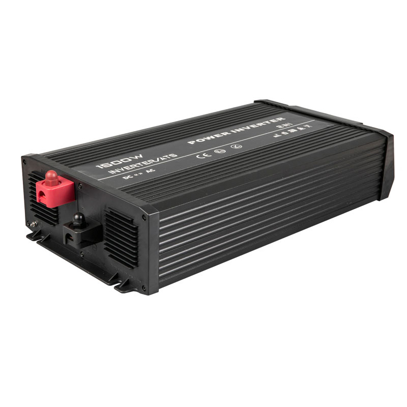
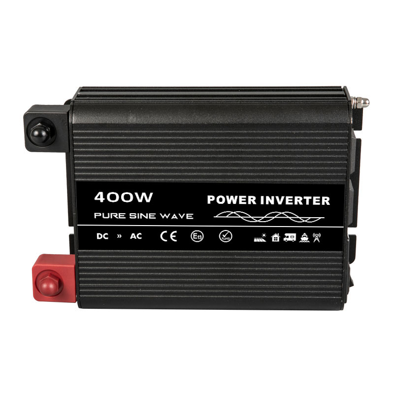
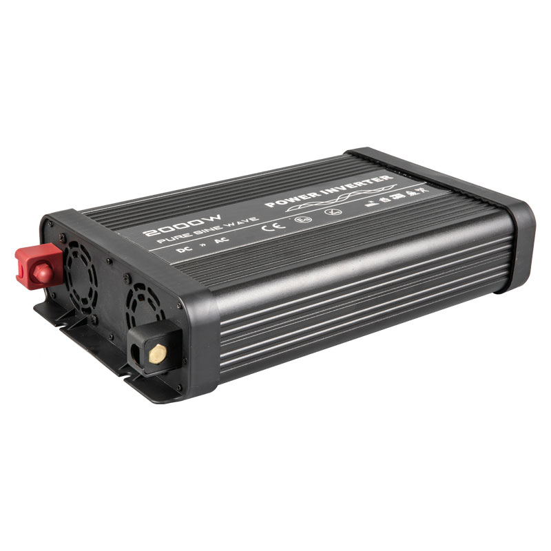
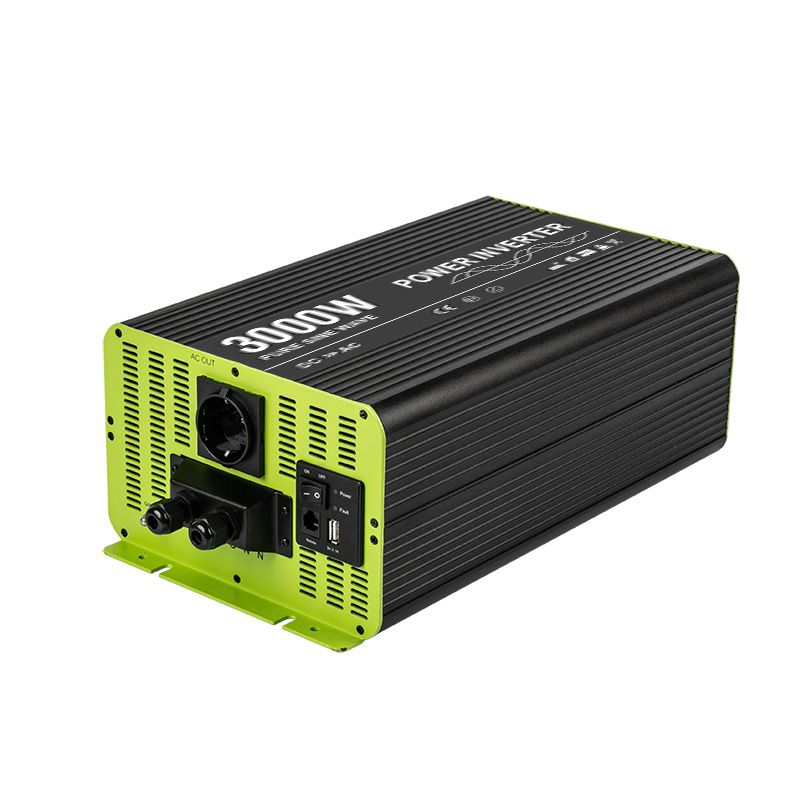
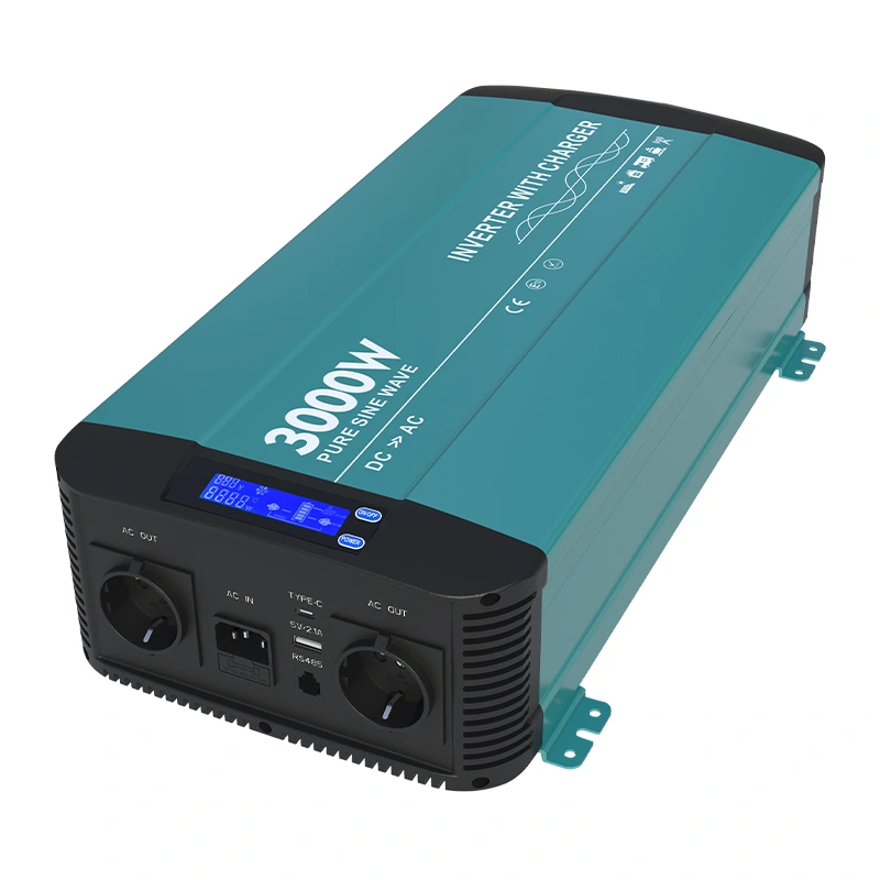
Many remote power installations face challenges when coordinating separate inverters and external battery chargers, as mismatched timing or incompatible voltage thresholds can degrade battery health and reduce overall system stability. 3000w Pure Sine Wave Inverter With Charger HK3000PC merges DC‑AC inversion and AC‑DC battery charging inside a single compact chassis, removing the complexity of coordinating multiple discrete power components for off‑grid, mobile or standby power projects. All‑in‑one units streamline wiring layouts and cut down points‑of‑failure within the energy chain, which brings tangible advantages for users working with camper setups, remote work sites, and residential backup configurations where continuous power availability carries high practical importance. When assembling standalone power systems, every added cable and separate device creates potential weak spots, so consolidated hardware architectures deserve careful consideration during planning phases.
1. Understanding combined inverter‑charger unit fundamentals
A combined inverter‑charger serves two primary roles within a storage‑based power ecosystem. First, it takes direct current stored inside lead‑acid or lithium battery banks and converts it to alternating current matching standard household electrical equipment specifications. Second, whenever external AC source becomes accessible, the onboard charger circuit draws power from grid or generator supply to refill connected battery packs automatically. This dual‑role design eliminates requirement for users to manually switch between standalone charger hardware and inverter modules.
- Seamless switch between battery‑powered inversion and mains‑driven charging workflows
- Unified LCD panel to visualize critical runtime metrics including voltage and wattage readings
- Integrated AC circuit breaker built into the main AC input pathway for supplementary circuit safety
- Dedicated USB‑A and Type‑C ports offering convenient low‑voltage direct device charging
Physical dimension and weight play meaningful roles for installers. The unit occupies 489 × 252 × 118 millimeters and weighs 8.8 kilograms, making wall‑mount deployment feasible for both stationary and mobile enclosures. Mounting brackets integrated onto the metal casing simplify secure fastening onto solid surfaces, whether users configure hardware within utility closets, vehicle compartments or outdoor sheltered cabinets. Proper clearance around ventilation grilles must always be maintained; obstructed airflow will trigger thermal protections and restrict available output capacity under heavy operating loads.
2. Output waveform quality and real‑world load compatibility
Pure sine‑wave output forms one of the most important differentiators compared against modified‑sine alternatives. Total harmonic distortion kept below five percent replicates waveform characteristics supplied by public utility mains. This matters greatly when running sensitive consumer electronics, inductive motors, refrigeration compressors and laboratory‑grade equipment. Devices containing motor windings or complex internal control boards often run hotter, produce additional noise or exhibit shortened service lifespan when fed distorted modified‑sine power signals.
Rated continuous output reaches 3000 watts with surge capacity reaching 6000 watts sustained for two‑second intervals. Surge rating handles the high inrush current that occurs the instant inductive appliances start spinning their motors. Without adequate surge headroom, inverters can trip overload protections every time compressors, water pumps or washing‑machine motors attempt startup cycles. Factory configurable output voltage options cover 100‑120VAC and 200‑240VAC families alongside selectable 50Hz or 60Hz frequency settings to match regional electrical norms. Minimum full‑load conversion efficiency registers at 89 percent, while peak operational efficiency climbs as high as 92 percent. Higher efficiency translates to less energy wasted as heat, preserving stored battery capacity for actual end‑user loads instead of thermal losses inside power electronics.
3000w Pure Sine Wave Inverter With Charger HK3000PC supports complete galvanic isolation between input DC side and AC output circuits. Full input‑output isolation adds an important safety layer, limiting fault propagation in case of ground faults or wiring mistakes inside connected battery circuits. This isolation feature receives high praise among professional installers constructing systems for locations with elevated electrical‑safety risks, such as marine environments and mobile vehicle applications where condensation and vibration increase chances for accidental short‑circuit events.
| Performance Parameter | Specification Value |
|---|---|
| Continuous AC Output Power | 3000 W ±5% |
| Surge Peak Power Duration | 6000 W for 2 seconds |
| Total Harmonic Distortion | Below 5% |
| Full‑Load Minimum Efficiency | 89% |
| Maximum Overall Efficiency | Up to 92% |
3. Integrated charging system and three‑stage battery management
The internal AC‑DC charger follows classic three‑stage charging logic: bulk constant‑current phase, absorption constant‑voltage phase and float maintenance phase. This well‑established charging profile optimizes recharge cycles for lead‑acid battery chemistries. During bulk phase, charger delivers maximum permitted current to rapidly lift battery voltage upward. Once target absorption voltage threshold is hit, unit transitions into absorption stage, holding steady voltage while charging current naturally tapers downwards. When current falls to roughly ten percent of rated charging magnitude, hardware enters float stage, applying lower maintenance voltage to counteract self‑discharge without overcharging cell plates.
Power‑factor correction achieves values greater than 0.95 under maximum charging load. Strong power‑factor performance reduces reactive power draw coming from the AC source, placing gentler demand upon portable generators or limited‑capacity grid outlets. AC input accepts wide‑range mains voltage; for 230VAC variant the operational AC input window spans from 180VAC up to 260VAC. Broad input tolerance means charger can keep functioning even when generator output drifts outside ideal nominal values, which frequently happens on portable generator hardware operating under fluctuating load conditions.
Charging current maximum differs according to DC‑input voltage variant. Twelve‑volt DC models support up to forty‑amp charging output, while twenty‑four‑volt DC versions deliver up to twenty‑amp charging output. System designers should match charger maximum current against recommended charge rate published by battery manufacturers. Excessively high charging currents accelerate battery degradation; conversely, under‑sized charging current prolongs recharge times unnecessarily. Careful pairing of battery bank capacity with charger capability ensures optimal long‑term battery cycle‑life performance.
4. ATS transfer performance and system continuity during power shifts
Built‑in automatic transfer switch (ATS) handles switching between battery‑derived AC power and incoming external mains supply. Transfer time registers below 16 milliseconds. Most common household electrical appliances tolerate brief interruptions of this magnitude without powering fully off. This characteristic delivers near‑UPS‑grade continuity for many connected loads. Users should keep in mind that certain highly‑sensitive industrial computing hardware may still require additional true‑online‑UPS units upstream if zero‑millisecond transfer becomes an absolute operational requirement.
Internal relay hardware handles the physical circuit switching tasks. Relay ratings differ across product variants: 110VAC configurations implement 30‑amp rated relays, and 230VAC models deploy 16‑amp rated relays. AC circuit breaker integrated on the mains‑input side provides over‑current disconnection protection for incoming AC feed, supplementing relay safety. When mains power returns after an outage event, ATS logic automatically routes loads over to external AC source simultaneously activating internal charger circuit to replenish battery energy reserves. This hands‑off behaviour makes hardware well‑suited for unattended remote installations where human operators cannot respond quickly to grid‑restoration events.
5. Built‑in protection layers for long‑term operational reliability
Robust multi‑layer protection suite safeguards both the inverter‑charger hardware itself and connected battery and load equipment. On DC input side protections cover reverse‑polarity defense via internal fuse, low‑voltage cutoff and over‑voltage shutdown conditions. Reverse‑polarity protection offers critical defence against installer wiring mistakes when connecting heavy‑gauge battery cables. Without such safeguard, reversed battery terminals can permanently destroy power conversion electronics in moments.
On AC output side the unit responds to short‑circuit occurrences, sustained overload situations and internal over‑temperature events. Whenever internal temperature climbs beyond safe operational ceiling, thermal protection triggers shutdown procedure to prevent permanent component damage. Temperature‑and‑load regulated cooling fans adjust rotational speed dynamically. Fans only spin faster under heavy workload or high internal temperature; under light‑load conditions fan noise stays minimal, an important benefit for indoor residential or cabin installations where acoustic comfort matters to occupants.
Every protective condition triggers visible feedback signals through front‑panel LCD display, allowing troubleshooting without opening equipment casing. Being able to read fault codes directly from local screen speeds diagnostic work for on‑site technicians servicing remote power sites. 3000w Pure Sine Wave Inverter With Charger HK3000PC consolidates many different protective responses inside single unit, removing requirement to stack many separate external protective modules around the power system architecture.
6. Hardware communication ports and remote monitoring possibilities
An RS‑485 communication port with RJ‑11‑style physical connector enables remote monitoring capability. Users may optionally attach an external remote LCD control panel positioned away from main inverter‑charger chassis. This proves convenient for installations where main power hardware sits inside basement storage compartments or utility cabinets, while operators wish to observe status readings from living‑area spaces. Ethernet connectivity exists as an optional upgrade for more‑advanced supervisory setups.
Through RS‑485 bus, host monitoring systems can pull real‑time datasets including battery voltage, output wattage, operational mode flags and active fault indicators. For system integrators constructing larger micro‑grid deployments, this opens pathways to integrate hardware into higher‑level site‑monitoring platforms. Keep in mind that RS‑485 wiring practices should respect industry guidelines for long‑distance differential signalling; proper cable selection and grounding help avoid data corruption caused by electrical noise from nearby high‑current power conductors.
7. Suitable operating environments and mechanical installation notes
Full‑load rated ambient temperature range extends from zero degree Celsius up to plus forty degree Celsius. When surrounding temperature rises to sixty degrees Celsius, hardware automatically derates available output capacity down to seventy‑percent of nominal power rating. Storage temperature window spans zero up to seventy degree Celsius for non‑operational periods. Humidity tolerance reaches maximum ninety‑three‑percent relative humidity under non‑condensing environmental conditions. Condensation represents a major risk factor; locations experiencing dew formation must ensure adequate ventilation to keep internal circuit boards dry.
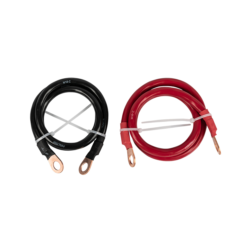
Mounting orientation must follow manufacturer mechanical drawings. Maintain sufficient clearance in proximity to fan ventilation openings so hot exhaust air can escape freely. Avoid sealing unit inside fully‑enclosed small cabinet without dedicated exhaust ventilation, as trapped heat activates thermal derating and frequent protective shutdown events. When selecting battery cable gauge, always account for high DC‑side current magnitudes associated with three‑thousand‑watt power levels; undersized cables introduce excessive resistive voltage drop and create dangerous overheating points along wiring runs.
8. Frequently asked technical questions
Yes. The AC input circuit will accept output from properly‑sized portable generators. Keep generator output voltage within the published AC‑input operating window. Be mindful of generator surge capability; generator continuous watt rating should comfortably exceed maximum charging plus auxiliary AC‑load draw simultaneously applied onto generator terminals. Poor‑quality generator output with extreme voltage fluctuation can trigger internal protective responses.
The native three‑stage bulk‑absorption‑float charging curve is originally engineered for flooded, AGM and gel‑type lead‑acid battery banks. When deploying lithium‑ion battery assemblies, users must verify battery management system compatibility against charger voltage set‑points. Some lithium packs require modified charging profiles; in such scenarios external dedicated battery charger hardware might become necessary.
Although internal reverse‑polarity fuse exists inside unit, industry best‑practices strongly recommend installing high‑current rated fuse directly on positive battery conductor within short physical distance from battery terminals. This external fuse protects battery cabling itself in catastrophic short‑circuit events external to inverter‑charger enclosure.
Galvanic isolation creates electrical separation between battery DC circuit and AC output circuits. This inhibits fault‑current flow across domains during ground‑fault incidents, improves safety within mobile and marine installations and reduces some categories of electrical noise coupling between battery bank and connected AC‑side devices.
9. Final thoughts for system integrators
All‑in‑one inverter‑charger hardware streamlines many off‑grid and backup‑power system builds by consolidating inversion, battery charging, automatic transfer switching and multiple protective functions into single chassis. When evaluating power conversion hardware, look beyond only continuous watt‑rate figures; take time to assess surge handling capacity, waveform purity, built‑in protection feature completeness, transfer‑switch timing and available monitoring interfaces. Each of these specifications shapes real‑world system reliability day‑to‑day.
Every power system project starts with thorough load auditing. Document wattage draw for every appliance expected to run, note inductive loads with large startup inrush currents, and define acceptable battery discharge depth limits before selecting battery bank and inverter‑charger combination. Thoughtful pre‑planning prevents operational frustrations after hardware installation completes. 3000w Pure Sine Wave Inverter With Charger HK3000PC fits nicely for projects requiring three‑thousand‑watt continuous output while wanting integrated charging capability without assembling a patchwork collection of separate power‑system components.
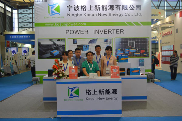
For professional‑grade manufacturing background behind this hardware you may explore resources published by Ningbo Kosun New Energy Co.,Ltd. Engineering documentation, dimension drawings and full specification sheets provide further depth for technical evaluators preparing system designs.
contact us